Planning advice

Tip 1: heat recovery
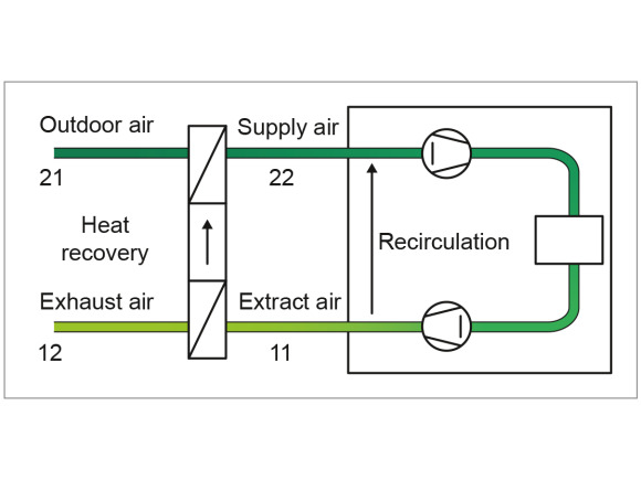
Here, it is important that no pollutants are transferred, as any contamination of the fresh air greatly reduces the effect of the ventilation system. For this reason, recirculation is not a form of heat recovery.
Heat recovery not only saves energy and, therefore, costs, but also reduces pollutant emissions during heat generation. This ecological aspect has already led to the use of heat recovery units being required by law in the European Union (EU).
It is important for some units to transfer air humidity as well as heat. This allows dry fresh air to be humidified by humid extract air or humid fresh air to be dehumidified by dry extract air. This also saves energy on air-conditioning systems.

Indirect fresh air cooling
Tip 2: indirect fresh air cooling
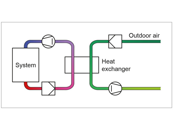
Heat recovery units are also used for other applications. One example is the cooling of systems with high internal heat loads, such as data centres. If the servers are heated excessively, they have to be cooled. An excellent solution in terms of energy efficiency here is indirect fresh air cooling with plate heat exchangers. The cold fresh air cools the recirculated air stream without transferring soiling.
If the fresh air temperature is not low enough, it can be additionally lowered by means of adiabatic water evaporation. This increases the cooling capacity, meaning that mechanical cooling can often be omitted. It is important to note that no fresh air is supplied to this system and there is no exhaust air.

Two wheel principle for air-conditioning of warm, humid fresh air
Tip 3: air-conditioning of warm, humid fresh air
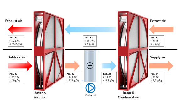
Heat recovery units can also be combined – for example, to dry humid and warm fresh air and then reheat it to the required supply air temperature using the heat from the extract air.
To do this, two wheels (a sorption wheel and a condensation wheel) are connected to a cooling coil in series. The humid, warm fresh air (21) is precooled and predried in sorption wheel A by the cooled extract air (12). This results in state 22.
State 23 is achieved with the cooling coil by means of mechanical cooling. The supply air is cooled to such a degree that the required humidity is reached due to condensation.
This temperature is too cold for the air to be blown into the room, so it is reheated to state 24 in condensation wheel B.
It is important that sorption wheel A transfers a large amount of humidity, but condensation wheel B should not transfer any (it could be replaced by a plate heat exchanger). This option is recommended for warm and humid fresh air, such as in the Middle East.

Tip 4: leakage
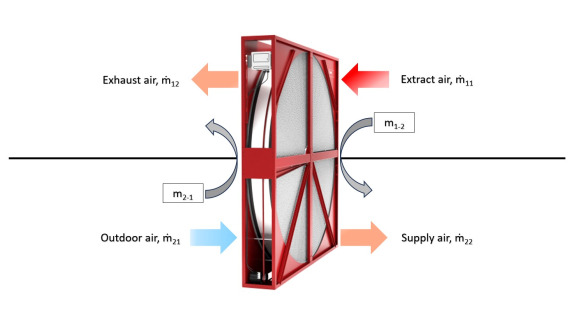
The transfer of partial mass flows from one air stream to the other is referred to as (internal) leakage. It is caused by leaks as a result of a pressure difference (seal leakage) or is function-related, such as carryover in a rotary heat exchanger.
Due to the internal leakage, the mass flows of extract/exhaust air and fresh/supply air are changed; this has many effects:
- The extract air and fresh air streams must be adjusted according to the leakage.
- This causes an increase of the air flow rate of the fans.
- Due to the leakage from the extract air to the supply air, the quality of the supply air can be impaired.
- Due to the leakage, the configuration conditions of the heat recovery unit and thus its technical data (temperature efficiency, pressure drop) are modified.
Because of these effects, the leakage must be kept as small as possible. The planner can make a decisive contribution to this by ensuring a low pressure drop (from the fresh air to the exhaust air). The heat recovery unit manufacturer, on the other hand, can play their part with high-quality sealing systems.
Two indicators are used to define and compare the leakage:
Exhaust Air Transfer Ratio: EATR = (m22 – m2net)/m22
m22 = mass flow of supply air
m2net = m22 – (all mass flows from extract/exhaust air in fresh/supply air)
m2net is the proportion/amount of fresh air in the supply air and depends on the pressure differences and function (carryover). EATR states how much extract air is in the supply air; it is therefore an indication of the quality of the supply air.
Outdoor Air Correction Factor: OACF = m21/m22
m21 = mass flow of fresh air
OACF states how much fresh air is flowing into the exhaust air or how much exhaust air is flowing into the fresh air and how the fresh air stream needs to be adjusted as a result.
These indicators can also be used to define limit values. The following apply (as of 11/2024):
EATR: max. 0.05
OACF: 0.9–1.1
Tip 5: condensation in the extract air
If humid air is cooled down, the relative humidity rises until condensate is formed. This has various effects on heat recovery.
Temperature efficiency
At low outdoor temperatures, humid extract air is cooled down by the fresh air to such a degree that the saturation temperature is reached and condensate is formed. Condensation heat is released, i.e. the cooling of the extract air stream is reduced. This increases the temperature difference between extract air and supply air, meaning more heat is transferred. Condensation also increases and improves heat transfer, and the temperature efficiency increases accordingly. The extent of this increase depends primarily on the dry temperature efficiency of the heat exchanger and on the amount of condensate, i.e. the air conditions of fresh air and extract air.
Pressure drop with condensation
Condensation creates droplets or a water film on the extract air side. This reduces the free cross-section. The pressure drop increases as a result and can account for up to 50% of the value during dry operation. It should therefore be taken into account in the design.
Risk of freezing
Under extreme conditions, i.e. at very low outdoor temperatures, the condensate produced can freeze and thus possibly put the heat recovery unit out of operation. During the design phase, the relevant manufacturer’s information on this subject should be taken into account.
Design
In ventilation units, it is important that the condensate produced is separated from the air stream, collected and discharged. It is therefore important to check whether a condensate separator is required in the exhaust air to separate any droplets that have been carried along. In order to avoid the transfer of condensate to the supply air, a pressure drop towards the extract air should be planned.
Tip 6: frozen condensate
If humid extract air is cooled down, the relative humidity rises until condensate is formed. If the fresh air is so cold that the extract air is cooled below the freezing point of the condensate, it can freeze and block the heat exchanger on the extract air side partially – or in extreme cases even completely.
The freezing limit, which is the minimum permissible fresh air temperature at which freezing does not yet occur, depends on:
- the extract air conditions (temperature t11 and humidity rh11 or x11)
- the (dry) temperature efficiency of the heat recovery unit
- the mass flow ratio (m2 : m1 = cold air : warm air)
- the exchanger design
The freezing limit can be calculated (approximately); however, practical applications reveal that the actual freezing behaviour also depends on other factors in addition to the physical boundary conditions.
Characteristic curve of the extract air fan
Freezing narrows the flow cross-section of the extract air and the pressure drop increases. In fans with a flat characteristic curve, this reduces the warm mass flow and the heat exchanger ultimately freezes up completely. In a fan with a steep characteristic curve, approximately the nominal extract air volume is still conveyed even if the fan has a smaller flow cross-section, so the heat exchanger does not generally freeze up completely. The ventilation function is guaranteed – although with some limitations.
Mounting position and air flow
The theoretical calculation does not take into account the fact that the condensate in the heat exchanger is moved not only by gravity, but also by the flow forces. In principle, this can have two effects:
- The condensate produced is warm and rich in energy. This means that colder parts of the heat exchanger can be kept free of ice if there is sufficient condensate.
- If the amount of condensate is too small, the heat exchanger freezes faster due to the supply of condensate.
Possibilities for avoiding ice
If it must be ensured that the heat exchanger is always fully functional, the following measures are possible to prevent freezing:
- Preheating the fresh air
- Changing the mass flow ratio
- Thawing circuits
All measures reduce the overall heat recovery efficiency. From an economic point of view, however, this is of little importance, as the risk of freezing normally occurs only during a few operating hours per year.
Tip 7: humidity transfer
- In wintry conditions (low absolute humidity in the fresh air), it is usually an advantage if the humidity in the extract air is transferred to the dry fresh air. Even if this humidity transfer is rarely considered in the economic efficiency calculation due to the lack of specifications, it makes a considerable contribution to increasing comfort.
- In all systems with controlled room air humidity (minimum, maximum), humidity transfer significantly reduces energy consumption and investment costs. The heat recovery unit works in the same way for both heat and humidity in that it acts as a rectifier between the extract air and fresh air; during the winter, the fresh air is humidified, while in summer conditions, it is dried.
- In systems with mechanical cooling, the necessary cooling capacity is calculated based on the summer conditions. So if humidity transfer (in this case by means of drying the fresh air) enables the required cooling capacity to be reduced, this results directly in a reduction in the investment, as this is generally greater than the additional expenditure required for humidity transfer in the heat recovery system.
Tip 8: condensate tightness and resistance
- The condensate has to be collected and discharged so as not to damage the building fabric (floors, ceilings, roofs, etc.).
- The condensate contains pollutants; therefore, it has to be disposed of/treated correctly.
- If condensate reaches the supply air side due to tiny leaks, the supply air will be contaminated. (The impact of condensate leakage is generally much greater than air leakage.)
- In terms of material resistance, condensates are often much more aggressive than gaseous media. It is vital to check whether the materials used (seals!) are resistant to the condensate.
- Arrange condensate drip trays on the exhaust air and supply air sides.
- Keep the pressure difference as small as possible.
- Measure the pressure difference in the direction of the exhaust air stream.
- Use particularly tight/tested heat recovery units.
- During cooling, it is possible for condensate to also develop on the fresh air side.
Tip 9: risk of contamination
Based on decades of operational experience, it is generally to be noted that all heat recovery units demonstrate better results in terms of soiling than was initially to be expected.
For “normal” applications – such as offices, hotels, banks, but also assembly halls, swimming pools, industrial warehouses – there are no problems whatsoever with regard to soiling. Nowadays, heat recovery units are even being used successfully in kitchen extraction systems, paint shops, welding fume extraction systems, and similar applications, provided appropriate precautions such as double filtering, automatic cleaning, etc. are taken.
Until now, the following applications have proved problematic in terms of soiling:
- Fibres, such as those in textile manufacturing
- Viscous condensate from solvents and greases
- Compounds of condensates and dust
- Paint particles that have not dried sufficiently
However, solutions are available for these applications too, although the cost-effectiveness must be reviewed in these cases.
Depending on the soiling, heat recovery units can be cleaned with a brush and vacuum cleaner, with warm water, air pressure, water and steam jets, or even with solvents. It is important that the heat exchanger is not damaged by cleaning. This applies with respect to both material resistance and strength. Particular care is required when using air pressure, water jet and steam jet equipment.
Heat recovery units requiring regular cleaning must be installed in such a way that:
- they are easy to access when installed and the soiling is easy to remove (provide drain) and/or
- they allow the exchangers to be removed easily for cleaning
Tip 10: temperature resistance
Tip 11: output control
It is necessary to control the heat recovery output if the supply air temperature is heated above the required room temperature due to internal heat loads. In other words, output control can only be omitted if:
- no/few heat loads are present
- cooling is taking place
The output can always be controlled by a bypass and, in some systems, also by means of unit-specific measures – such as speed control on the rotary heat exchanger. In practice, a bypass is used in many cases. The reasons for this are as follows:
- If a bypass for exhaust air and fresh air is used, the system can also be operated without a heat recovery unit (operational safety).
- When operating with a bypass, the heat recovery unit does not become dirty.
- The bypass can also avoid the risk of freezing.
Tip 12: operational safety
Tip 13: corrosion resistance
The materials that can be used if there is a high risk of corrosion are coated aluminium, stainless steel, plastic and glass. In extreme conditions, the main problems relate to adhesives and sealants.